Robotics in Go: Building a Raspberry Pi Rover
When we consider programming languages for robotics, those that come to mind often include established players such as C and C++, Python, or even those specifically designed for scientific and numerical computing, such as MATLAB. In this post, we look at Go as a viable programming language for robotics.
This post builds upon content I presented at the Melbourne Go Meetup on May 14, 2026. My talk centred around a project called Rover Kit, a small rover that uses Go for motor control and sonar readings. The Rover Kit source code has been published on GitHub. The Rover Kit v0.1.0 release contains the version of the code discussed below.
Contents
- Introduction
- Bare Metal Robotics
- Hardware Interfaces
- Go Libraries
- Rover Kit
- Motor Control
- Sonar Reader
- Web Bridge
- Next Steps
- References
Introduction
So much of the appeal of robotics is its breadth as a subject. It touches upon mathematics, mechanical and electrical engineering, and (of course) software. Just as broad are the many different kinds of robots we can build. The most ambitious include bipedal humanoid robots, actuated robots that operate in factories, or even surgical devices.
The Hardware
This post focuses on a small rover that includes four DC motors (driven by an Adafruit Motor HAT) and several HC-SR04 ultrasonic distance sensors. The chassis and wheels are from a Whippersnapper Runt Rover kit. With everything connected, the rover looks something like this:
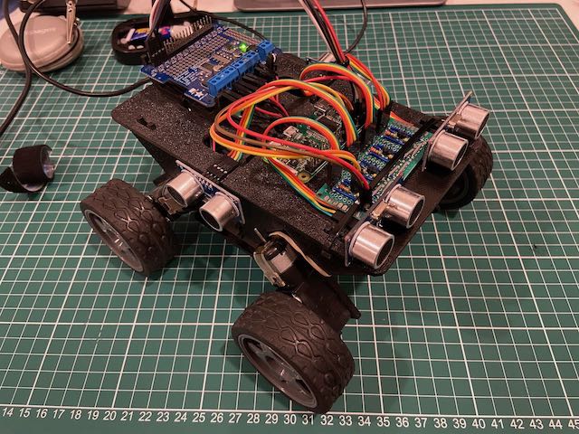
Hidden within the chassis is a 12V battery pack to power the DC motors.
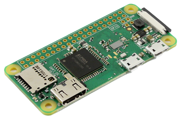
It also includes a 5V USB power supply that powers a Raspberry Pi Zero W - this is the brains of the operation:
Although fairly modest as far as robotics is concerned, this kit allows us to explore the software stack while steering clear of advanced topics (e.g. inverse kinematics and frames of reference).
Robotics Fundamentals
A typical robot incorporates actuation (wheels, motors, or other moving parts), sensors to perceive the environment, and some degree of planning and control. Tying this all together are software systems that ensure the robot achieves the task it was designed to do.
The demands placed on robotics software are non-trivial. They include:
- Real-time control - operating within precise timing constraints
- Embedded environments - low power and harsh operating conditions (heat, dust, moisture)
- Probabilistic planning - working with sensor data that might be noisy or incomplete
- Safety systems and critical infrastructure - ensuring safe and correct operation, under a wide range of conditions
To address these concerns, large-scale hardware projects will often turn to a mature robotics framework that offers component isolation, message passing, device drivers, diagnostics, and deployment tooling.
A popular choice today is ROS, otherwise known as the Robot Operating System.
Robot Operating System
ROS provides middleware, standard message types, navigation and perception packages, and tools for visualisation and debugging. It also offers broad device support, which makes it appealing for research and prototyping.
ROS has historically had two major release lines. ROS 1 was built around a central roscore process, but reached end-of-life in 2025. ROS 2 moved away from that central control node architecture and added features aimed at commercial and industrial robotics, including QoS, device discovery, and improved security.
Message Passing
A common theme, though, is message passing. ROS 1 and ROS 2 are both designed around message passing as a core concept. Individual components can be responsible for just one aspect of a robot’s behaviour, with components coordinating towards larger goals by publishing and subscribing to different topics on a message bus:
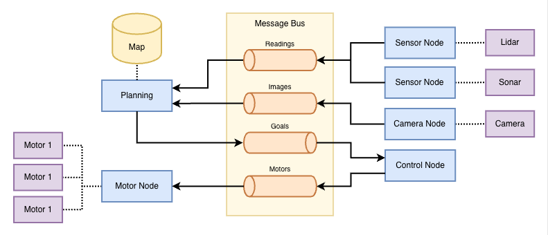
Although the message passing concept has proven scalable and robust, ROS itself has a steep learning curve. It also comes with resource demands that may strain small devices. This complexity may distract from the actual goal of a hobbyist: having fun with a project that combines hardware and software. For that we want something more akin to “bare metal robotics”.
Bare Metal Robotics
Bare metal robotics captures the notion of doing robotics with as little overhead as possible.
Python is a common choice for hobbyist robotics, thanks in part to its simplicity. Python features a wide range of libraries for GPIO communication and other hardware interfaces. However, a major drawback is performance, as it suffers from being an interpreted language. Deployment can also be challenging, due to the number of dependencies that must be installed on the target device.
Go for Robotics
It turns out that Go is also a great option for bare metal robotics.
While it may not be perfect, Go has several properties that make it an appealing choice:
- Concurrency model - goroutines and channels offer a clean mapping to asynchronous sensor/actuator loops
- Memory safety - no pointer arithmetic and a memory-safe runtime make it safer than C++ (for many classes of bugs… in theory)
- Simplicity & readability - Go is often easier to read than C++ or Python
- Cross-compilation - often produces self-contained binaries with minimal runtime dependencies
- Iteration - fast builds, simple dependency management, good testing support
The concurrency model and support for cross-compilation are two of the most interesting properties (in my opinion!).
Concurrency Model
Robots combine multiple activities that are conceptually independent, but must coordinate with one another to achieve various tasks. A simple robot may combine sensors, actuators (e.g. motor controllers) and basic navigation. Each of these components (or processes) needs to run concurrently.
Go’s concurrency model maps nicely to that problem. A goroutine can own a long-running activity, such as sampling a sonar sensor once per second, while a channel becomes the handoff point for the values it produces. In turn, Go’s treatment of channels as first-class language features leads to several nice concurrency patterns.
Go’s context package also provides clean shutdown semantics. Commands can create a context tied to SIGINT or SIGTERM, pass it down into individual goroutines, and block until cancellation.
Cross-Compilation
Cross-compilation is another major benefit! The Go compiler makes it extremely easy to cross-compile binaries that run natively on the Raspberry Pi Zero W.
The compiler provides built-in support for ARMv6, which is the instruction set used by the Pi Zero. Cross-compilation is as simple as running go build on your host machine with the appropriate command line arguments and environment variables:
env GOOS=linux GOARCH=arm GOARM=6 \
  go build -ldflags "-w" -o bin/motor-control cmd/motor-control/main.go
Go Drawbacks
The primary drawback of Go is the garbage collector (GC), which can lead to unpredictable latency spikes. Timing discrepancies can impact perception and coordination. For certain motor configurations, this could lead to overshooting or undershooting actuation targets.
While it’s possible to configure garbage collection, or even switch it off entirely, these are beyond the scope of this post.
Hardware Interfaces
Embedded devices support a range of hardware I/O interfaces, each designed to accommodate different hardware design goals. A common characteristic of the interfaces described below is that they are all serial.
Readers who are old enough may recall owning a computer that had both serial and parallel ports:
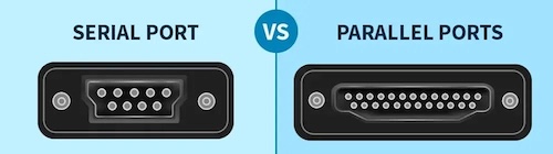
Image credit: Difference between Serial Port and Parallel Port by GeeksForGeeks
An obvious difference between the two ports is the number of pins required. The parallel port has a wider bus, which means it can transmit more bits at the same time, while serial is designed to transmit one bit at a time.
Serial may seem limiting, but it forms the foundation of various hardware interfaces. This includes the ubiquitous USB (Universal Serial Bus) and the GPIO pins commonly found on embedded devices.
GPIO
GPIO (or General-Purpose Input/Output) refers to a set of digital pins that can be controlled via software. In hobby electronics projects, it is common to wire up GPIO pins to LEDs, sensors, and other small components. Each SBC has its own GPIO pin configuration, such as this one for the Raspberry Pi:
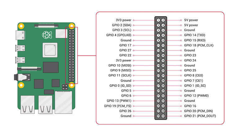
Image credit: How to Use Raspberry Pi GPIO Pins – Python Tutorial by Seeed Studio.
Groups of GPIO pins can be used to implement more sophisticated protocols or hardware interfaces. We’ll introduce some of those now.
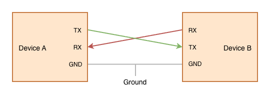
UART
One of the most common interfaces you’ll find on embedded devices is UART, short for Universal Asynchronous Receiver/Transmitter. UART is a protocol for serial communication between two devices, using separate transmit and receive signal wires plus a shared ground. Two UART devices are connected via cross-over wiring:
For signalling purposes, each character is preceded by a start bit (always a zero) and ends with one or more stop bits (logical ones). The signal line is held in the ‘one’ state when nothing is being transmitted:
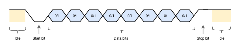
Standard UART data rates range from 9600 bits per second (bps) up to 115200 bps. High-speed UART implementations exist, but are less common. A more common alternative is USART, short for Universal Synchronous/Asynchronous Receiver-Transmitter, which includes an additional clock wire for synchronisation, enabling faster transfer rates.
SPI
SPI (Serial Peripheral Interface) is a fast synchronous serial bus commonly used to talk to chips on the same board. In a typical setup, there is one SPI controller, which is responsible for communicating with one or more SPI peripherals. Peripheral chips are each targeted using a dedicated chip select pin, often labelled CS or SS.
The following diagram shows three SPI peripherals wired up to a single SPI controller. Note the presence of three CS/SS pins:
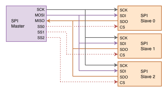
Examples of SPI peripherals include displays, sensors, and storage devices (think SD cards). When working with embedded devices you may encounter SPI Flash, a kind of non-volatile flash memory that is capable of retaining data without power. SPI Flash is well suited to storing data and program code that needs to be loaded when a device is first powered up.
I²C
I²C (Inter-Integrated Circuit) is a two-wire synchronous serial bus designed for connecting multiple chips via the same circuit.
Unlike SPI, I²C is an addressed bus, which means that individual chips are targeted via an address encoded into the bitstream. Chips are connected to the bus via two wires: serial data (SDA) and serial clock (SCL). It is assumed that there is an I²C controller which controls the bus and clocks data from target devices when reading.
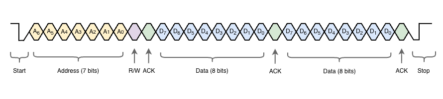
A start of a frame consists of a 7-bit address, a read/write bit which indicates whether the controller is sending or receiving data, and an ACK bit. The control then sends data, or receives data, depending on the R/W bit.
The Adafruit Motor HAT in this project uses an I²C-based PWM driver chip. This means that, with just two signal wires connected to the Raspberry Pi, we can control four DC motors!
Go Libraries
We’ve seen above that Go can be used to target platforms such as the Raspberry Pi, BeagleBone or Jetson Nano, and we’ve introduced some of the hardware interfaces available on these devices. The next question is how we can make use of those hardware interfaces.
This section will look at three in detail: Gobot, Periph and Serial. These are the three libraries used in Rover Kit.
There are many others we could look at (such as gpiocdev which gets an honourable mention), but unfortunately we don’t have time to cover them all.
Gobot
Gobot is a robotics framework for Go that provides APIs for devices, sensors, and actuators across a wide range of platforms. Using the provided drivers and adaptors, you can write higher-level behaviour once and retarget from one board or device family to another with minimal changes.
The following example uses the firmata adaptor to control an LED connected to an Arduino:
package main

import (
  ...
)

func main() {
  firmataAdaptor := firmata.NewAdaptor("/dev/ttyACM0")
  led := gpio.NewLedDriver(firmataAdaptor, "13")

  work := func() {
    gobot.Every(1*time.Second, func() {
      led.Toggle()
    })
  }

  robot := gobot.NewRobot("bot",
    []gobot.Connection{firmataAdaptor},
    []gobot.Device{led},
    work,
  )

  // Start the main event loop
  robot.Start()
}
Gobot provides adaptors for a wide range of SBC devices, including the Raspberry Pi, BeagleBone, and Tinker Board. It also supports drones and robotics kits.
Periph
Periph is a low-level hardware I/O library for Go. It provides direct access to GPIO, I²C, SPI, PWM, and other interfaces commonly found on SBCs. It is especially useful when you want tight control of peripheral communication without needing a heavier robotics framework.
We will see later that Periph can be used to drive motors via the Adafruit Motor HAT, and measure distance using the HC-SR04 ultrasonic sensors.
Serial
The last library I want to mention is go.bug.st/serial, a cross-platform serial port library for Go.
As you can see, this library makes it easy to open and read from a serial device:
// configure
mode := &serial.Mode{
  BaudRate: 115200,
  DataBits: 8,
  StopBits: serial.OneStopBit,
  Parity:   serial.NoParity,
}

// open port
port, err := serial.Open("/dev/ttyACM0", mode)
if err != nil {
  return nil, err
}

// read bytes from UART connection
buff := make([]byte, 128)
bytesRead, err := port.Read(buff)
if err != nil {
  return nil, err
}
_ = bytesRead
This can be used to delegate reading from ultrasonic sensors to a separate microcontroller, which is something we’ll explore in a future post!
Rover Kit
In this section, we take a closer look at the hobby project that inspired this post: Rover Kit. The project adopts a modular architecture, with separate Go executables to drive motors, read sonar sensors, and send commands via a web interface.
MQTT provides pub/sub messaging between components:
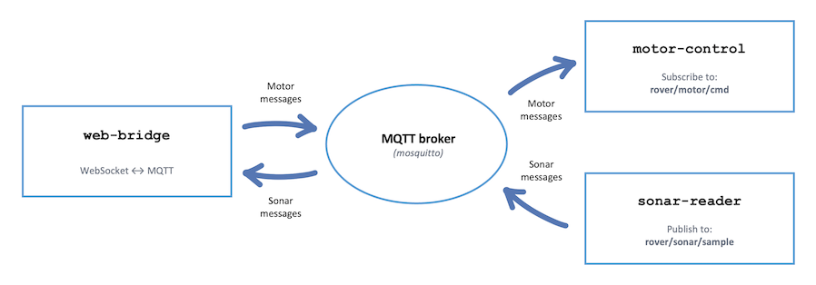
MQTT is a standard protocol for communication between IoT devices. This is similar to the message bus we saw in ROS, and has the advantage of being highly portable. At the time of writing, there are over 20 server implementations and even more client libraries.
MQTT Client
We make use of the Eclipse Paho MQTT Go client to connect to an MQTT broker and pass messages between components.
Basic connection:
client := mqtt.NewClient(opts)
connectToken := client.Connect()
connectToken.Wait()
if err := connectToken.Error(); err != nil {
  log.Fatalf("failed to connect to broker=%s err=%v", brokerURL, err)
}
Subscription example:
opts.SetOnConnectHandler(func(client mqtt.Client) {
  log.Printf("connected to broker=%s", brokerURL)
  token := client.Subscribe(motorCmdTopic, 1, subscriber(ctx, driver, gate))
  token.Wait()
  if err := token.Error(); err != nil {
    log.Printf("failed to subscribe topic=%s err=%v", motorCmdTopic, err)
    return
  }
  log.Printf("subscribed topic=%s", motorCmdTopic)
})
Publishing example:
s.mqttClient.Publish(defaultMotorCmdTopic, 0, false, message)
Peripherals
Recall that our rover hardware included:
- Four DC motors
- Four HC-SR04 ultrasonic distance sensors
The motor HAT is controlled over I²C through the Raspberry Pi’s GPIO header, while the ultrasonic sensors use ordinary GPIO pins. Rover Kit provides motor driver implementations for Gobot and Periph. Supporting both is not strictly necessary for such a simple project. However, it serves some pedagogical value by allowing us to compare the implementations side-by-side.
Project Structure
Rover Kit follows a standard Go project structure. The three commands live in cmd/, while supporting code lives in pkg/. There is no internal/ directory, as the project is intended to be completely open.
You will also find configuration files for deployment on the Raspberry Pi:
deploy/- systemd configuration filesmqtt/- mosquitto configuration files
A Makefile has also been included, making it very easy to cross-compile for ARMv6.
make
Next, we’ll look at the three commands: motor-control, sonar-reader, and web-bridge.
Motor Control
The motor-control command knows how to interact with our DC motors, via the Adafruit Motor HAT. This is backed by the Driver interface, which declares the main behaviours that we need to support for our four DC motors:
type Driver interface {
	Forwards(ctx context.Context) error
	Backwards(ctx context.Context) error
	SpinCW(ctx context.Context) error
	SpinCCW(ctx context.Context) error
	Stop(ctx context.Context) error
	Close(ctx context.Context) error
}
Pulse Width Modulation
Pulse Width Modulation (or PWM) controls a DC motor by rapidly switching the motor’s power supply on and off instead of varying the voltage directly.
You can picture this as a cycle. During the “on” part of each cycle, the motor receives 100% voltage. During the “off” part of the cycle, it receives no voltage. Because this happens so quickly, the motor behaves as if it is receiving an average voltage. The proportion of “on” vs “off” time is called the “duty cycle”. A 20% duty cycle means the motor is powered 20% of the time, and unpowered for the remaining 80%.
The Adafruit Motor HAT handles this for us. However, we still need to tell it what the desired duty cycle is for each motor. This is communicated via I²C.
Gobot Driver
Gobot provides an adaptor for the Raspberry Pi and an I²C driver for the Adafruit Motor HAT:
// Create an adaptor for the Raspberry Pi I2C interface
adaptor := raspi.NewAdaptor()
if err := adaptor.Connect(); err != nil {
  return nil, fmt.Errorf("connect raspi adaptor: %w", err)
}

// Initialise the motor hat driver
hat := i2c.NewAdafruitMotorHatDriver(
  adaptor,
  i2c.WithBus(1),
  i2c.WithAddress(defaultGobotMotorHatI2C),
)

// Start the driver
if err := hat.Start(); err != nil {
  _ = adaptor.Finalize()
  return nil, fmt.Errorf("start Adafruit motor hat driver: %w", err)
}
Although Gobot also offers a high-level event loop, we won’t use it for such a simple project. We simply send commands to the motor HAT, using a setMotor helper function:
func (d *GobotDriver) setMotor(motor int, throttle float64) error {
	t := math.Max(-1, math.Min(1, throttle))
	speed := int32(math.Round(math.Abs(t) * 255))

	if err := d.hat.SetDCMotorSpeed(motor, speed); err != nil {
		return err
	}

	switch {
	case t > 0:
		return d.hat.RunDCMotor(motor, i2c.AdafruitForward)
	case t < 0:
		return d.hat.RunDCMotor(motor, i2c.AdafruitBackward)
	default:
		return d.hat.RunDCMotor(motor, i2c.AdafruitRelease)
	}
}
Using the helper simplifies the implementation of individual actions, as we can see in Forwards below:
func (d *GobotDriver) Forwards(context.Context) error {
	d.mu.Lock()
	defer d.mu.Unlock()

	values := [4]float64{-1, 1, -1, 1}
	for i, value := range values {
		motor := i + 1
		if err := d.setMotor(motor, value); err != nil {
			return fmt.Errorf("forwards motor %d: %w", motor, err)
		}
	}
	return nil
}
Periph Driver
Another option is Periph, which also happens to support the PCA9685 chip on the Adafruit Motor HAT.
Unlike Gobot’s Motor HAT driver, we must manually specify the chip’s PWM motor configuration:
var periphMotorChannels = [4]periphMotorChannel{
	{pwm: 8, in1: 10, in2: 9},
	{pwm: 13, in1: 11, in2: 12},
	{pwm: 2, in1: 4, in2: 3},
	{pwm: 7, in1: 5, in2: 6},
}
The equivalent setMotor helper is a little more involved. Some error handling has been omitted for brevity:
func (d *PeriphDriver) setMotor(motor int, throttle float64) error {
	if motor < 1 || motor > len(periphMotorChannels) {
		return fmt.Errorf("unsupported motor index %d", motor)
	}
	ch := periphMotorChannels[motor-1]

	t := math.Max(-1, math.Min(1, throttle))
	duty := pwmDutyFromThrottle(t)

	switch {
	case t > 0:
		d.setChannel(ch.in1, true)
		d.setChannel(ch.in2, false)
	case t < 0:
		d.setChannel(ch.in1, false)
		d.setChannel(ch.in2, true)
	default:
		d.setChannel(ch.in1, false)
		d.setChannel(ch.in2, false)
	}

	if duty == 0 {
		return d.pca.SetFullOff(ch.pwm)
	}

	return d.pca.SetPwm(ch.pwm, 0, duty)
}
Sonar Reader
The sonar-reader command is responsible for taking readings from each of the HC-SR04 ultrasonic sensors. This is backed by the Provider interface:
type Reading struct {
	DistanceCM float64
	DurationUS float64
	Timestamp  time.Time
}

type Provider interface {
	Open(ctx context.Context) chan Reading
	Close(ctx context.Context) error
}
Sonar Sensors
Interacting with the HC-SR04 sensors is a little tricky, due to their timing sensitivity. Each sensor component has four pins, a transmitter (T / TX), and a receiver (R / RX):
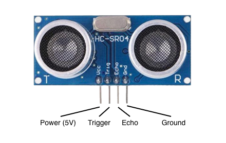
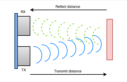
To measure the distance to the nearest obstacle, the transmitter first emits an ultrasonic pulse, then the receiver detects the echo of that pulse. The time between these two events is used to calculate the distance.
We can tell the sensor to emit a pulse by holding the trigger pin high for a short period. The sensor then raises the echo pin for the duration of a reflected ultrasonic pulse. Measuring that echo duration gives the round-trip travel time. We multiply by the speed of sound to calculate the total distance, then divide by two since we only want the distance in one direction:
Voltage Divider
It’s also worth noting voltage requirements. The HC-SR04 accepts 3.3V or 5V on the trigger pin, but the echo pin outputs 5V. However, the GPIO pins on the Raspberry Pi are not 5V tolerant. This means we must use a voltage divider to drop the voltage on the echo pin to 3.3V.
Voltage divider circuits are a dime-a-dozen online, and you’ll want to choose one that suits your particular hardware design. Here’s a photo from when I was halfway through soldering the small voltage divider board included in the rover:
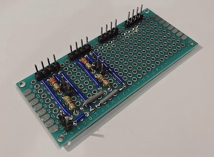
This iteration of the board supported two HC-SR04 sensors.
The final board supports four HC-SR04 sensors.
Periph Provider
Using Periph, we can interact with the HC-SR04 via GPIO pins on the Raspberry Pi:
// First we get references to appropriate GPIO pins:
trig := gpioreg.ByName("GPIO18")
echo := gpioreg.ByName("GPIO24")

// Example: Set trigger pin to low
trig.Out(gpio.Low)

// Example: Read from the echo pin
value := echo.In(gpio.Float, gpio.NoEdge)
To take sonar readings indefinitely, we use a for-ever loop inside a goroutine:
for {
  // set trigger pin high
  err := p.trig.Out(gpio.High)

  // sleep for long enough that the sonar will register the signal
  time.Sleep(triggerPulse)

  // set trigger low
  err = p.trig.Out(gpio.Low)

  // wait for echo high
  start := time.Now()
  for p.echo.Read() != gpio.High {
    if time.Since(start) > echoTimeout {
      log.Printf("timed out waiting for echo high")
      return
    }
  }

  // wait for echo low
  start = time.Now()
  for p.echo.Read() != gpio.Low {
    if time.Since(start) > echoTimeout {
      log.Printf("timed out waiting for echo low")
      return
    }
  }

  // calculate distance based on duration
  end := time.Now()
  duration := end.Sub(start)
  distance := duration.Seconds() * soundSpeedCMPerS / 2

  c <- Reading{
    DistanceCM: distance,
    DurationUS: float64(duration.Microseconds()),
    Timestamp:  time.Now(),
  }

  time.Sleep(sampleInterval)
}
UART Provider
Due to the timing-sensitive nature of ultrasonic readings, we also provide a UART provider. This can be used to gather readings from an external microcontroller (such as an STM32-based MCU).
We will look at how this works in the next post.
Web Bridge
Finally, we have the Web Bridge, which allows us to control the rover from a web browser. The web interface is intentionally small. It consists of a single HTML page (index.html), which loads a stylesheet and vanilla JavaScript:
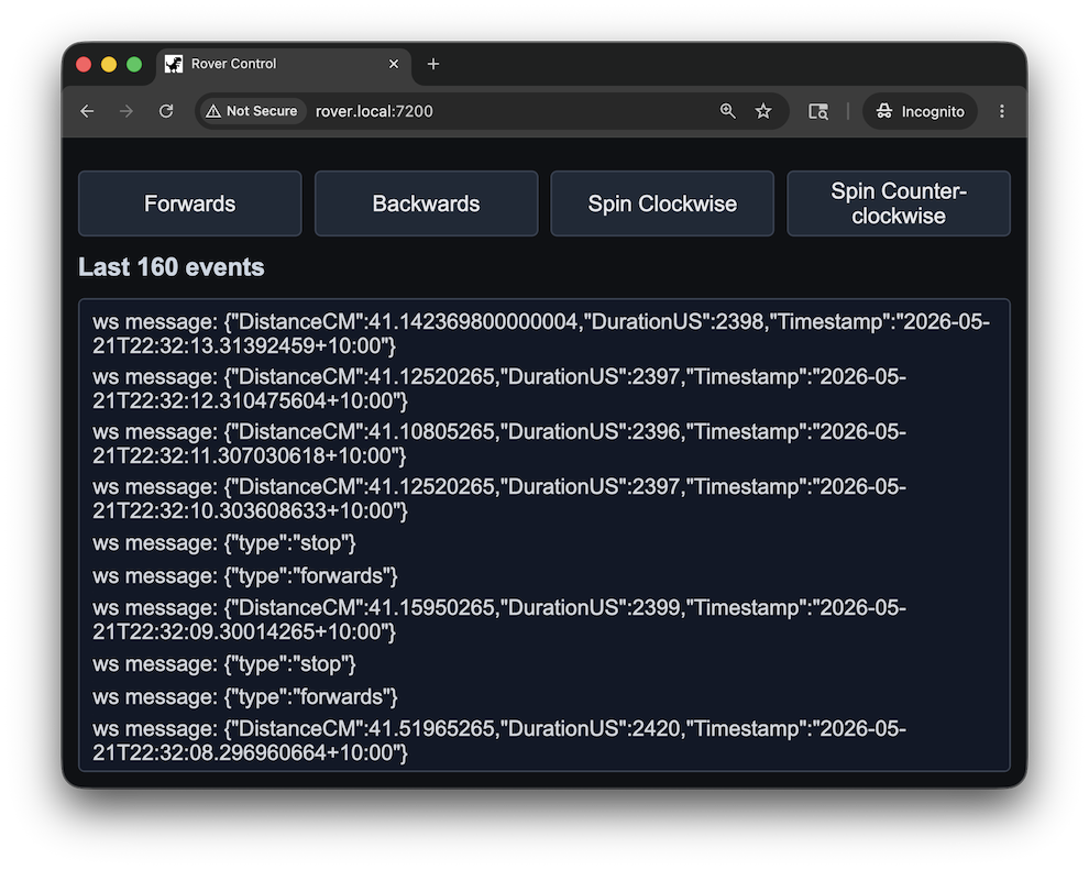
After loading, the web client opens a WebSocket connection back to /ws on the same host. This connection sends rover commands to the server and displays messages received from the server, including distance measurements.
WebSocket Server
The WebSocket endpoint is where the web UI meets MQTT. The web bridge is responsible for validating messages and publishing them via MQTT.
For example, when the browser sends the message {"type":"spin_ccw"}, the web bridge parses and validates the JSON payload. Malformed or unsupported payloads are rejected, and valid payloads are forwarded to the motor command topic (rover/motor/cmd).
The web bridge also subscribes to the sonar sample topic (rover/sonar/sample). When an ultrasonic reading is received, the web bridge publishes it to every connected WebSocket client.
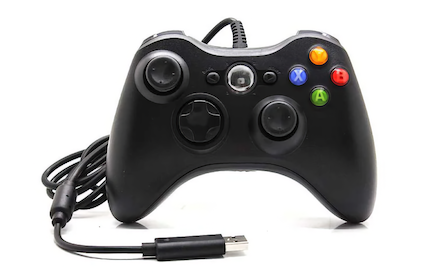
Gamepad Support
The web UI can also translate browser gamepad input into the same command messages used by the on-screen controls. This keeps the backend unchanged: whether a command comes from a button click, a keyboard shortcut, or a gamepad axis, the WebSocket server still receives JSON, validates it, and forwards it to MQTT.
For testing I used an Xbox 360 Gamepad, connected via USB:
Next Steps
The next challenge in this project is to delegate reading from ultrasonic sensors to a separate microcontroller. I will be using an STM32F407 Discovery Board, a common microcontroller development board based on the Arm Cortex-M4 processor. This will be used to send distance readings back to the Raspberry Pi via a USB UART connection.
Stay tuned for the next post, where we’ll use TinyGo to compile and run Go binaries on the STM32.
References
Libraries and frameworks:
- Gobot website - A framework for robots, drones, and the Internet of Things
- Periph website - A standalone hardware library with limited external dependencies
- Eclipse Paho MQTT Go client - Connect to an MQTT message broker from Go
Videos:
- Understanding I2C - Great ~10 minute video by Rohde & Schwarz
Embedded Go:
- Embedded Go - Bare-metal programming with Go
- Embedded Go STM32 - Support for the STM32 microcontrollers
- TinyGo - Bring Go to embedded systems and to the modern web using a compiler based on LLVM